CAD Tutorial - Autodesk Inventor
This tutorial is designed as a two session training exercise for rookie FIRST Robotics Competition students. Its purpose is to give a quick overview of the Inventor Professional software suite to allow anyone to quickly design or prototype a robot component before entering the shop. More in-depth tutorials are recommended for advanced features.
This tutorial is written for Autodesk Inventor Professional 2013, Education Version. Features may vary for differing releases.
Student Licenses of the software are available to all FRC members by signing up at: students.autodesk.com.
Day 1: Inventor Assemblies
Before diving into the software there are a couple items you must understand. First, what is Autodesk Inventor Professional? Inventor is a 3D solids modeling software package used for creating three-dimensional digital prototypes that aid in design, visualization, and simulation of robot components. That sounds like quite a mouthful, but don’t over think it. It really is easy.
Next, it is important to understand the basics of how Inventor works. There are two general file types in the software: Parts and Assemblies. A part is a single solid entity (i.e. a key on a keyboard) and an assembly is a collection of parts (i.e. all the keys, frame, etc.) constrained together. This may be slightly confusing, so the best way to understand the differences is to jump right into the software.
Please download the following folder, unzip, and save the entire contents to your computer.
| knex.zip |
Open Inventor.
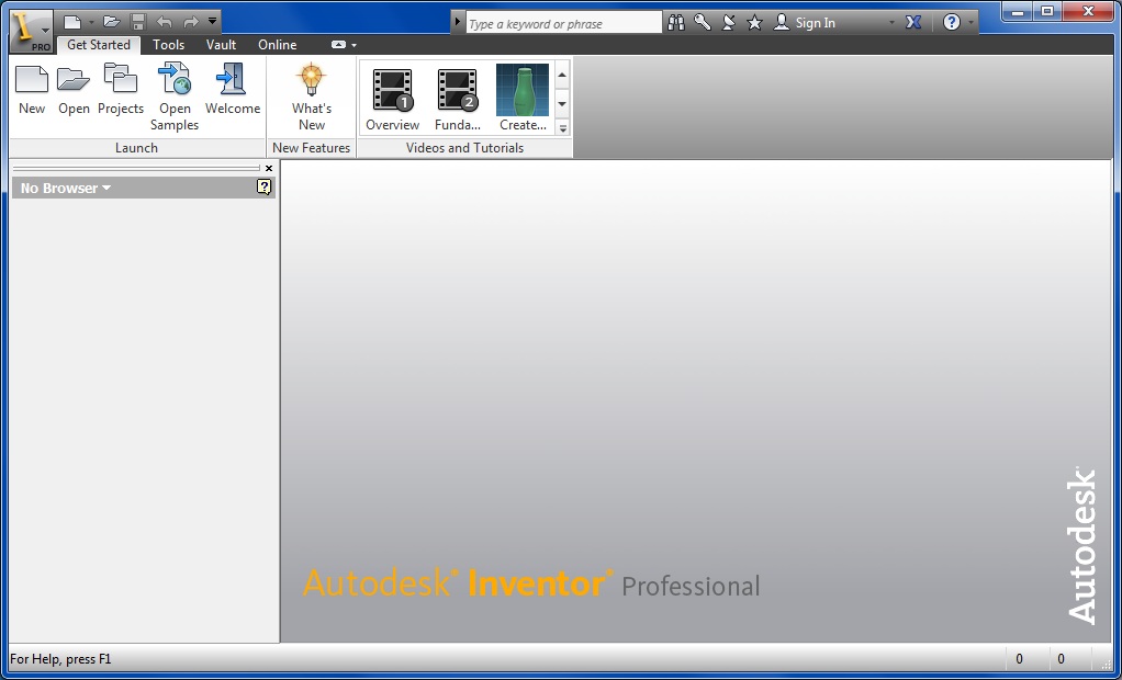
In this tutorial, we will use 3D models of K’nex to understand Assemblies and how to use the Inventor interface. Inventor’s user interface is set up similar to Microsoft Word’s Ribbon UI. Along the top there is a horizontal strip of various “Ribbons” or “Panels” that update based on what is selected and what features are most convenient for you. The vertical strip on the left is the “Browser”. More information about the browser to follow.
First, we must set up the project. In large assemblies (i.e. the full robot) there are thousands of individual parts. A project conveniently arranges all parts and subassembly files in one directory and eliminates any chances of saving / using files outside of the project directory. Select “Projects” under the “Get Started” Panel.
First, we must set up the project. In large assemblies (i.e. the full robot) there are thousands of individual parts. A project conveniently arranges all parts and subassembly files in one directory and eliminates any chances of saving / using files outside of the project directory. Select “Projects” under the “Get Started” Panel.
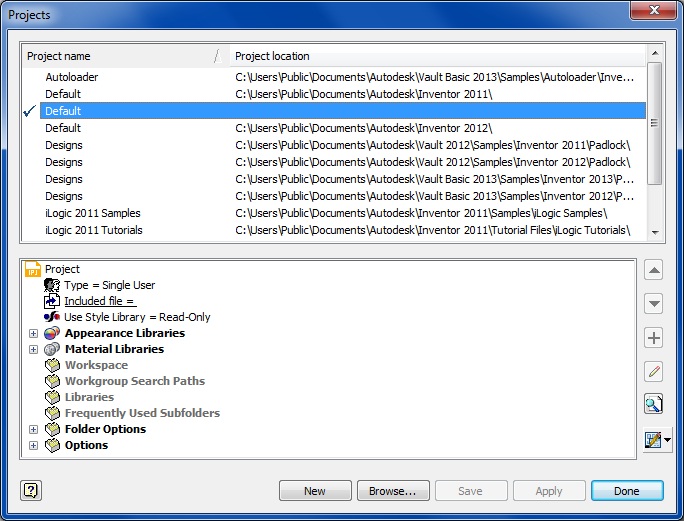
By default, the “default” project is selected. This essentially means there is no active project and files can be located anywhere your confused computer chooses. Luckily, a project file is already set up for you. Select “Browse…” and navigate to the folder you copied to your computer. Select the file titled “K’nex”. It will have a .ipj file extension. Verify there is a checkmark to the left of the K’nex Project. Select “Done”.
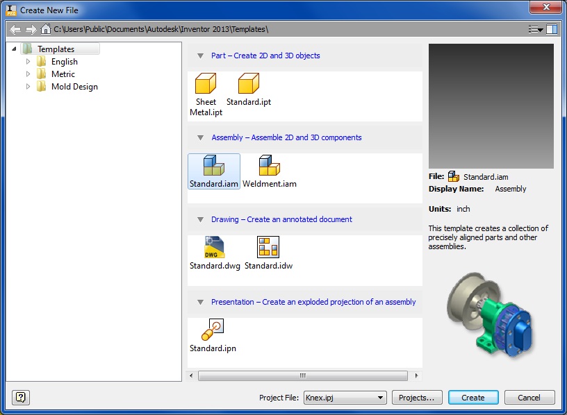
Select “New” under the “Get Started” panel. You are given 7 choices for file types. A beginner will only need to use two of these: parts and assemblies. Parts and assemblies have the file extension .ipt and .iam respectively. Select “Standard.iam”. Select “OK”.
Select “New” under the “Get Started” panel. You are given 7 choices for file types. A beginner will only need to use two of these: parts and assemblies. Parts and assemblies have the file extension .ipt and .iam respectively. Select “Standard.iam”. Select “OK”.
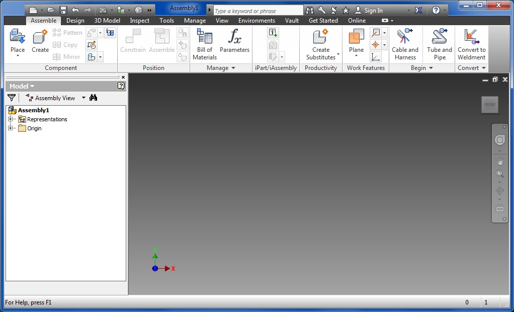
You will see a blank assembly open. Notice you now have more panels and your browser has contents.
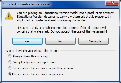
Select “Place” under the “Assemble” panel. Select “Blue Connector”. A message will appear as follows. This is okay. It is graciously reminding you that you are still in high school and only a student. You can select “Prompts” and choose “Do not show this message again ever” if you so wish.
Notice a blue connector part will automatically be placed in the center of your assembly. If you move around the mouse, a phantom piece will appear allowing you to insert more pieces. We only need one right now. Right click and select “Done” or press ESC.
Let’s discuss how to move around the model space. Scroll in and out using your scroll wheel. This is how to zoom in and out. Notice it will always zoom to the location of the cursor. Next is panning; press in the scroll wheel and move around the mouse. Rotating is similar. Select the “Shift” key and press the scroll wheel and move the mouse around. These are the three basic commands to move around the Inventor model space.
In addition, double clicking the scroll wheel will zoom to the entire extent of the model space. The ViewCube located in the top right corner of the model space can also be used to rotate. Press and hold any section of the cube and move the mouse around. Notice this will rotate the view. Also, selecting any of the sides, edges, or corner of the cube will change the view to the respective viewing angle. There is a “home view” identified by a small house to the upper left of the ViewCube. This is a viewing orientation that can be set as you wish. By default it is set on an isometric view. Also note when a front, side, top view is selected, the cube will give you more options.
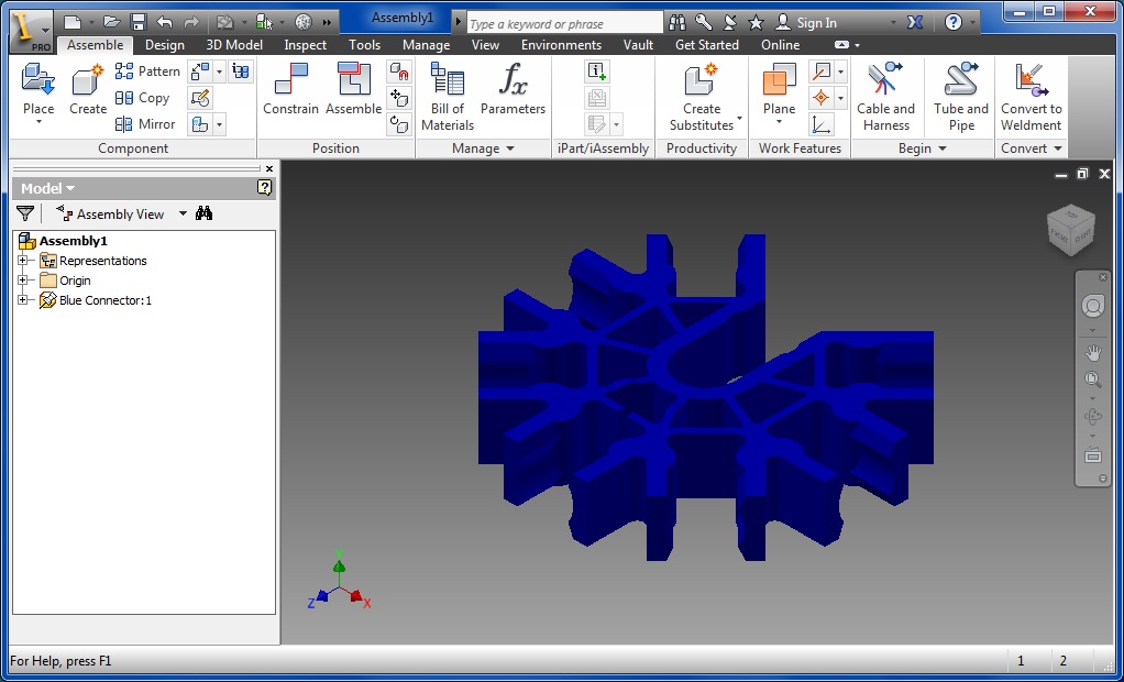
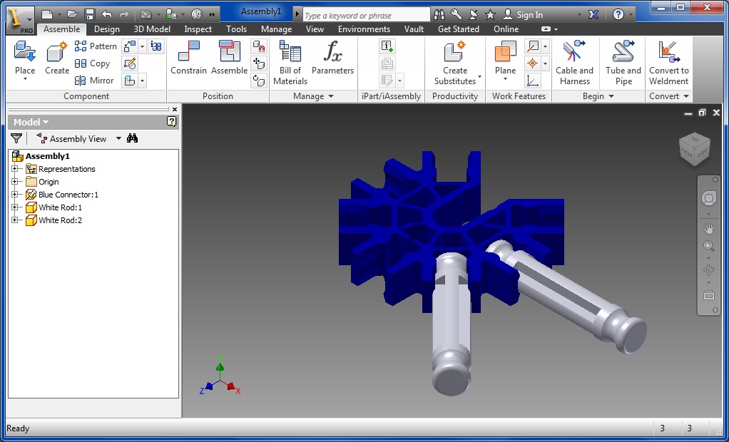
Now, let’s insert a couple more knex pieces. Select “Place” under the “Assemble” Panel. Choose “White Rod”. Notice this time it doesn’t automatically place a part. Place two pieces by left clicking at two locations. Again you will see a phantom piece (as shown below) after you inserted the two white rods. Right click and select “Done” or press ESC.
In addition, double clicking the scroll wheel will zoom to the entire extent of the model space. The ViewCube located in the top right corner of the model space can also be used to rotate. Press and hold any section of the cube and move the mouse around. Notice this will rotate the view. Also, selecting any of the sides, edges, or corner of the cube will change the view to the respective viewing angle. There is a “home view” identified by a small house to the upper left of the ViewCube. This is a viewing orientation that can be set as you wish. By default it is set on an isometric view. Also note when a front, side, top view is selected, the cube will give you more options.
Now, let’s insert a couple more knex pieces. Select “Place” under the “Assemble” Panel. Choose “White Rod”. Notice this time it doesn’t automatically place a part. Place two pieces by left clicking at two locations. Again you will see a phantom piece (as shown below) after you inserted the two white rods. Right click and select “Done” or press ESC.
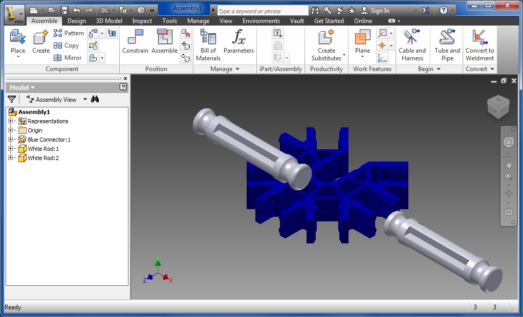
Take a look at your Browser on the left of the screen. It lists the three parts you placed. One “Blue Connector” and two “White Rods”. The browser essentially lists everything you’ve added to your assembly.
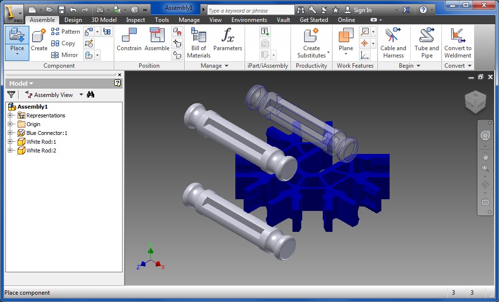
Select one of the white rods. It will change colors. This means you are good at selecting parts. If needed, you can delete the part by pressing the “delete” key. You can also select multiple parts by holding the “shift” key and selecting each one individually. Now move around one of the white rods by pressing and holding the cursor over it. This will independently move the piece. Now select the white rod again. Under the “Assemble” Panel there is an icon for rotating an individual piece. It is located in the “Position” subcategory as shown below. Left click and drag anywhere inside the circle. Notice this will rotate the individual piece. When you think it looks pretty, right click and select “Done”.
Select one of the white rods. It will change colors. This means you are good at selecting parts. If needed, you can delete the part by pressing the “delete” key. You can also select multiple parts by holding the “shift” key and selecting each one individually. Now move around one of the white rods by pressing and holding the cursor over it. This will independently move the piece. Now select the white rod again. Under the “Assemble” Panel there is an icon for rotating an individual piece. It is located in the “Position” subcategory as shown below. Left click and drag anywhere inside the circle. Notice this will rotate the individual piece. When you think it looks pretty, right click and select “Done”.
Grab the Blue Connector and try to move it. Notice it won’t let you. This is because the part is grounded. The first part you insert in a new assembly is always grounded. You know it is grounded because in the browser there is a pushpin over the part’s icon. It is important to always have one part grounded. To ground/unground a part, right click on the component and select “Grounded”. If need be, you can ground multiple parts, but it is recommended that one part is grounded at all times.
Now it is important to understand that in Assemblies, the multiple components must be constrained to each. We already found out that the Blue Connector is fixed in place. This is a good start. Our next challenge is constraining a rod to the connector. Select “Constrain” under the “Assemble” panel. You will see the options shown below.
Now it is important to understand that in Assemblies, the multiple components must be constrained to each. We already found out that the Blue Connector is fixed in place. This is a good start. Our next challenge is constraining a rod to the connector. Select “Constrain” under the “Assemble” panel. You will see the options shown below.
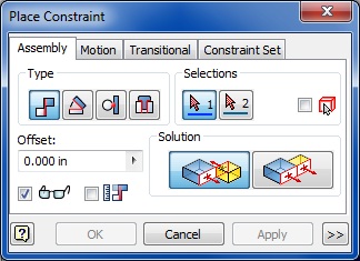
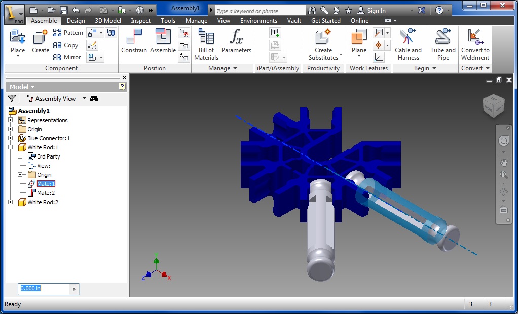
There are many types of constrains to apply. The simplest one, which is what we will use, is the mate constraint. The mate constraint, simply put, takes two faces and essentially glues them together. For example, put your hands together. You just applied a mate constraint to the palms of your hands. By default this type of constraint is selected. Move the cursor over the parts various faces and edges. Notice the cursor will change. This chooses which face we apply a constraint to. This may be a little tricky, but start by selecting one of the curved surfaces on the connector as shown below. Notice when you hover over the curved surface an axis appears.
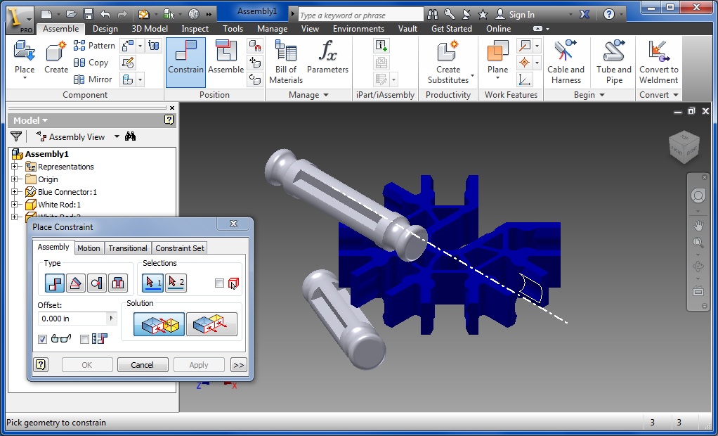
Next select the curved surface of the rod. It is important that you select the actual surface and not one of the edges. Remember you are looking for an axis to appear down the center of the rod, which will appear as a dotted line. Sometimes it is easier to zoom in to the component to ensure you select the face. After selecting the rod, the constraint will snap the rod to be on the same axis as the first face you selected. Once your model looks like what is shown below, select “OK”.

Now grab the rod and try to move it around. Notice it only moves along the axis we selected. Position it similar to the picture below.
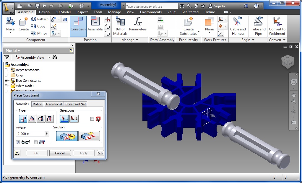
We want to add one more constraint to prevent the rod from sliding on the axis. Select “Constrain”. This again will be a mate. Select the face of the connector as shown below. Now rotate the view so you can see the opposite face on the rod. (Hold “Shift” and press in the scroll wheel”) Again It is important to actually select a flat face. When hovering over the edge of the rod you may see a small dot appear, this means you are not selecting a face. The two faces will snap together, select “OK”.
Try to move around the constrained white rod. Notice it only rotates but it physical position is fixed. You have successfully constrained your first two parts. Now try it again using the second rod. Insert a few more connectors and rods and constrain them.
TYPICAL ERRORS / CLARIFICATIONS / TRICKS:
Deleting Constraints:
Expand the menu next to the component you want to delete a constraint. If there are multiple constraints you can select each to verify the mate you wish to remove. Right Click and select “Delete”.
Expand the menu next to the component you want to delete a constraint. If there are multiple constraints you can select each to verify the mate you wish to remove. Right Click and select “Delete”.
I Lost My Browser:
I don’t know how you guys always close this, but select the “View” panel, select “User Interface” and check off the “Browser”.
Why do I have to navigate to the knex parts every time I place a new part?
Set up your project. That is always your first move. Like tying your shoes. Always do it first.
Patterning Parts:
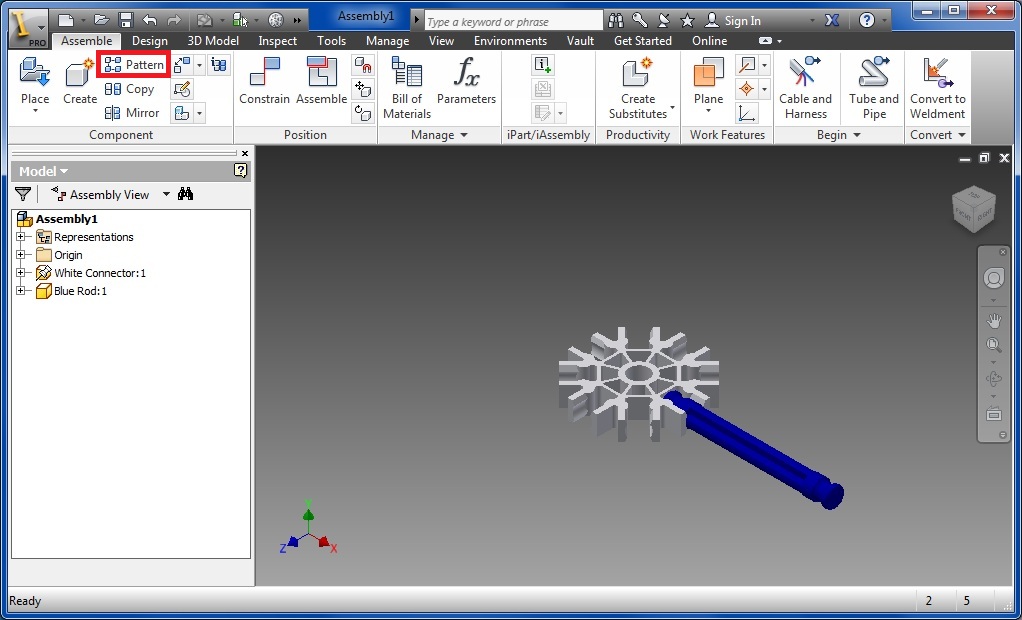
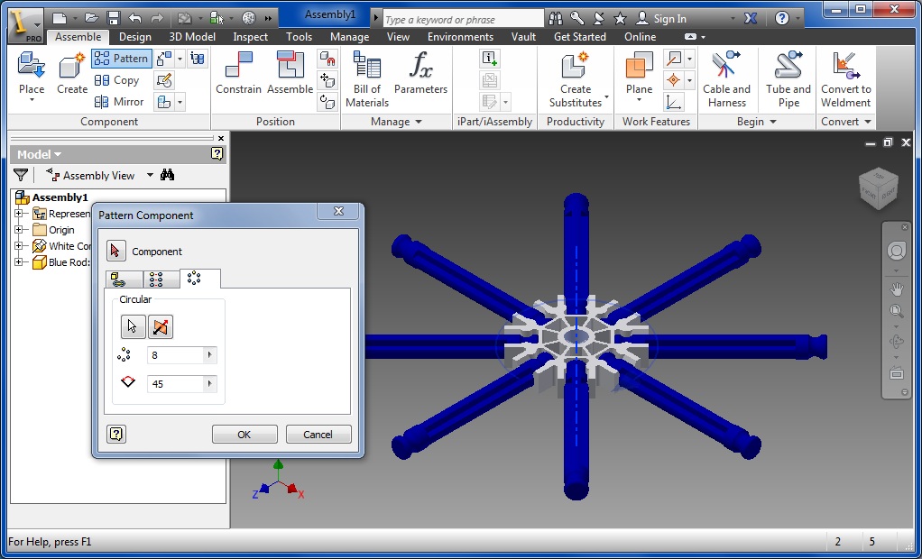
This is a time saving trick. Let’s say I want to place 8 blue rods around a white connector as shown below. Let Inventor do it for you. Apply the first constraint as described previously. Next select “Pattern” under the “Assemble” Panel. Choose the third tab that shows a circle, which means Inventor will pattern the part around a given axis. Select the blue rod. Under the word “Circular” you will see a pink arrow. When there is a pink arrow it means something needs to be selected. Notice that when you selected the rod, the arrow next to the word “Component” became white. Hover over the white connector near its center. It will look similar to the cursor for placing constraints as shown below.
I don’t know how you guys always close this, but select the “View” panel, select “User Interface” and check off the “Browser”.
Why do I have to navigate to the knex parts every time I place a new part?
Set up your project. That is always your first move. Like tying your shoes. Always do it first.
Patterning Parts:
This is a time saving trick. Let’s say I want to place 8 blue rods around a white connector as shown below. Let Inventor do it for you. Apply the first constraint as described previously. Next select “Pattern” under the “Assemble” Panel. Choose the third tab that shows a circle, which means Inventor will pattern the part around a given axis. Select the blue rod. Under the word “Circular” you will see a pink arrow. When there is a pink arrow it means something needs to be selected. Notice that when you selected the rod, the arrow next to the word “Component” became white. Hover over the white connector near its center. It will look similar to the cursor for placing constraints as shown below.
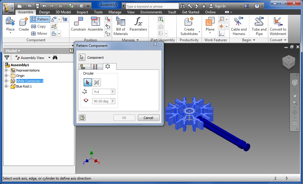
By default you will see 4 new blue pieces arrayed around the connector. Change the setting as shown below to have 8 total pieces with 45 degrees between.
Note that multiple components can be patterned at once. For example if you have a rod with a gray connector on the end, you can select and apply the array to both.
Modeling a Knex Contraption:
Now that you are an expert in creating constraints with Knex, select one of the following to model: Knex Vehicles or Miscellaneous Knex Models
Day 2: Inventor Sketches
Coming Soon!
Modeling a Knex Contraption:
Now that you are an expert in creating constraints with Knex, select one of the following to model: Knex Vehicles or Miscellaneous Knex Models
Day 2: Inventor Sketches
Coming Soon!
|
Useful Shortcuts
General Shortcuts F1 Help Topics F2 Pan F3 Zoom F4 Orbit F5 Previous View Shift+F5 Next View F6 Home View F7 Slice Graphics in Sketch F8 Show All Constraints F9 Hide All Constraints Esc Ends Active Command Home Zoom All Page Up Look At Delete Delete selected object End Zoom Select Ctrl+/ Origin Axes visibility toggle Ctrl+] Origin Planes visibility toggle Ctrl+. Origin Points visibility toggle Alt+/ User Work Axes visibility toggle Alt+] User Work Planes visibility toggle Alt+. User Work Points visibility toggle Sketch Shortcuts A Center Point Arc C Center Point Circle D General Dimension F Fillet L Line O Offset X Trim = Equal |
Modeling Shortcuts E Extrude F Fillet H Hole Ctrl+Shift+K Chamfer Ctrl+Shift+L Loft Ctrl+Shift+M Mirror Ctrl+Shift+O Circular Pattern R Revolve Ctrl+Shift+R Rectangular Pattern S 2D Sketch Ctrl+Shift+S Sweep ; Grounded Work Point / Work Axis ] Work Plane . Work Point Assembly Shortcuts C Constraint (Assembly) Ctrl+Shift+E Degrees of Freedom visibility toggle G Rotate Component Ctrl+H Replace Ctrl+Shift+H Replace All N Create Component in Assembly P Place Component in Assembly Ctrl+Enter Return / Work Axis ] Work Plane . Work Point |