Weekly Build Season Videos
Chairman's video
Robot Summary
|
DRIVE TRAIN
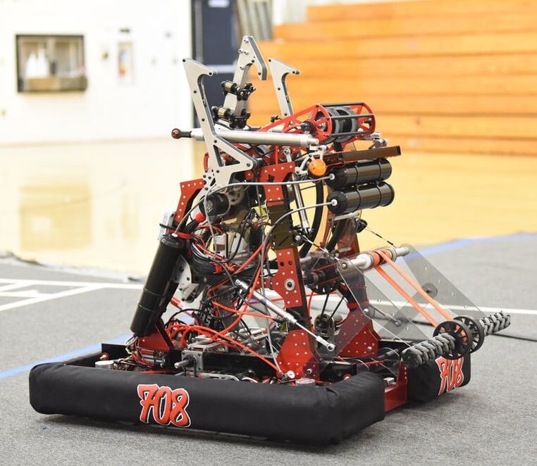
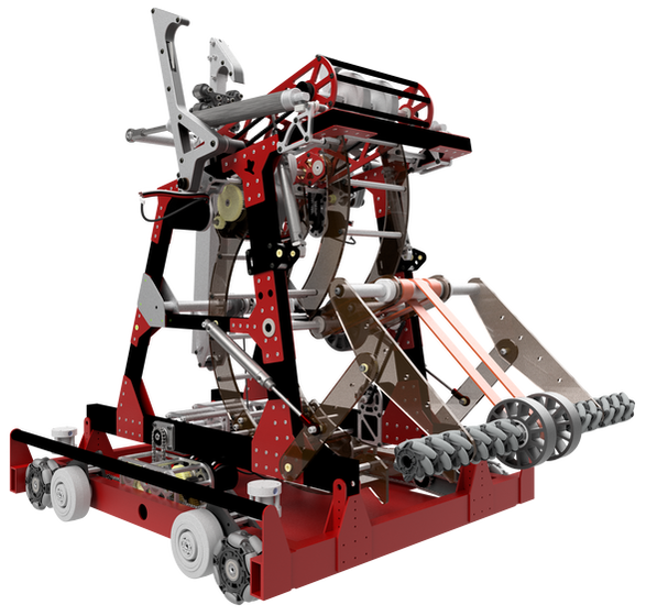
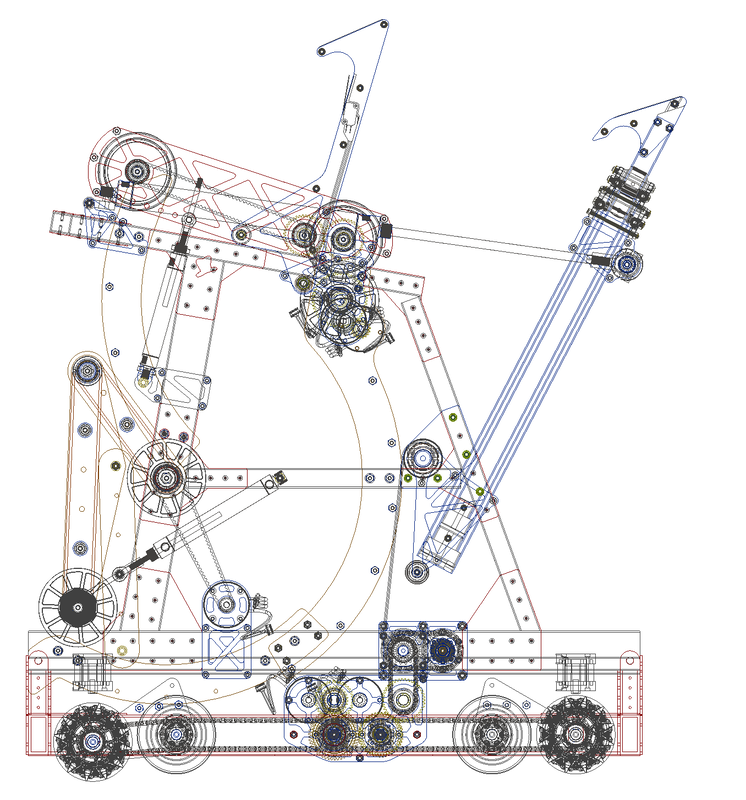
Our drivetrain is a butterfly drive, allowing us to switch between omni wheels and colson high-performance wheels using custom drop modules. This drive train style allows us to have high mobility while maintaining the simplicity and power of a tank drive. Using custom gearboxes, our drive train can shift between 12 and 18 feet per second. INTAKE The intake extends out over the bumpers and uses mecanum wheels to center the cargo through a gap in the bumper. Orange polyurethane belts pull the cargo into the ball path. The four-bar intake structure folds within the frame perimeter and is built from polycarbonate plates to allow for flexibility and durability to sustain impacts from robots. A-FRAME
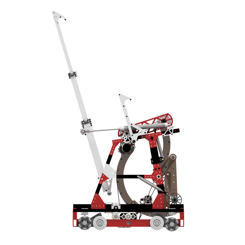
All our subsystems, excluding the drive train, are located on the A-frame of our robot. The A-frame can be fully detached from the robot quickly and easily, allowing simultaneous maintenance on the drive train and the A-frame. CLIMBER To climb, we extend the articulating hook to grab the rung. Then, we retract the articulating hook and pivot it into our robot so that the one-way door hooks engage the rung. Next, we pivot the articulating hook and extend it to the next rung. The articulating hook is retracted, which restarts the process. ONE-WAY DOOR HOOKS We have two passive hooks located on the top of our A-frame with built-in limit switches. These act as one-way doors, snapping closed once pressure is applied, to allow us to lock onto the rungs while moving with the articulating hook. |
BALL PATH
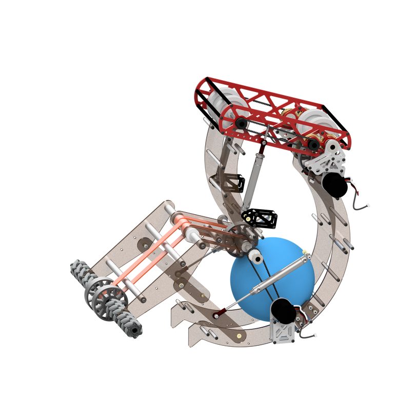
The ball path is an efficient S-shaped system that stores two cargo and transitions the cargo from intake to the shooter. Compliant wheels pass the cargo along polycarbonate rails to maintain consistent contact. SHOOTER A double wheel shooter with two positions gives the ability to shoot in both the upper and lower hubs from anywhere on the field. It is comprised of 4” diameter colson high-performance wheels and powered by two neos. INTEGRATION Our cargo management system was designed with integration in mind. Each subsystem seamlessly feeds into the next, minimizing jams or other issues and allowing the robot to work as one cohesive unit. ARTICULATING HOOK
Our articulating hook is a three-stage arm, with the tubes sliding by utilizing bearing blocks. The hook is spring loaded using constant force springs which allow it to quickly extend. It can then be retracted by utilizing a power takeoff and a winch system. There are air cylinders that pivot the hook. SHARED POWER In order to power our climber without adding additional motors, we decided to create a power take off using the drive train’s gearboxes. A shifter inside the gearboxes transitions power to the climber system. 3-D PRINTING We utilized our new 3-D printer to prototype many different systems of our robot, including the feeder, drive train, and shooter. A 3-D printer allowed us to quickly create parts we needed based on just the CAD files using carbon fiber-infused filament. |
Strategy
- The day of kickoff, we read the entire Rapid React manual so that we all would understand the rules of the game that we had to design the robot for.
- The next day, we spent the entire meeting having a conversation about our strategy for the game. We discussed the benefits of the upper and lower hubs, our plans for what our autonomous program could look like, and other strategy-related topics. We also discussed some of the features that had to be on our robot, including that we needed to be able to hold two cargo balls, and that we needed to be able to climb to the traversal bar.
- On Monday, we then discussed how we could apply this strategy to actual systems and came up with five different subsystems for our 2022 robot: Intake, Feeder, Shooter, Climber, and Drivetrain. We soon began prototyping our designs for these systems.
- After we had our prototypes, we had discussions on the pros and cons of each design, and how those would be reflected in our strategy. We discussed how certain intakes would better fit the strategy of allowing other robots to feed us and discussed the pros and cons of selecting the two drive trains we were considering: swerve drive and butterfly drive.
- In the end, we felt that a robot with a butterfly drive better fit the strategy we wanted for this game. We also decided on an intake that gave us the freedom to implement many different strategies for acquiring cargo, including being fed by other robots. Our climber allows us to climb to the traversal bar, maximizing our endgame points.
Drivetrain - butterfly
Robot Architecture - A-Frame
- When we were designing the final robot, we needed to design how we were going to mount all of our upper systems to the drive train of the robot. We knew that we wanted the middle to be open to give space for the ball path. In addition, we determined that the shooter had to be a certain height above the ground, or a certain distance away from the end the ball was being shot out of to allow us to shoot over other robots and into the hub easily.
- We ended up finding that the best structure to fit our needs was having an A-frame on either side of the robot that supported all of the robot’s subsystems, excluding the drive train. The two metal frames are separated to allow for the cargo to be transported through the feeder, which resides between them, and into the shooter, which sits on the top.
- The A-frame is completely removable from the drive train of the robot by removing just four bolts. This allows for simultaneous maintenance of the drive train and the A-frame. This was especially helpful during final assembly, as both major portions of the robot could be worked on at the same time by two separate groups, allowing us to give our software team significantly more time than normal with the robot, due to us finishing most of the subsystems significantly quicker than we usually do.
- The removable A-frame also allows us significantly better access to the electronics and pneumatics located on the top of the drive train. By removing the A-frame, we have nothing covering these key components, allowing for easy maintenance.
Ball Management & Integration
- This year, a major focus for the two teams working on the subsystems that dealt with cargo was the integration between subsystems to allow for a seamless transition between the intake, feeder, and shooter.
- The intake and feeder subsystem were designed by the same group of people, with one subsystem lead, to ensure that the cargo easily was transferred from the intake to the feeder.
- To further ensure the integration of the various cargo management subsystems, the upper feeder wheel was designed by the shooter group based on the initial idea of the feeder group. This ensured that cargo was transferred into the shooter in the way that would best fit our shooter design.
- We also had many group discussions with both the intake/feeder group and the shooter group throughout the design process to ensure our systems worked well together. Both groups were always fully aware of the progress of the other group, and major design choices were shared between teams to ensure every choice worked for all parts of the cargo management system.
intake prototyping
- Our intake has six mecanum wheels on each side, feeding the cargo into the center by pressing it against the bumper. In the center of the intake, two compliant wheels launch the ball into polyurethane belts that pull the ball directly into our feeder.
- This was the first season that we have used the polyurethane belts. We spent a considerable amount of time working to find the perfect amount of tension for the belts on the intake. Eventually, we settled on taking the distance that we wanted for the belts, decreasing the length by 5-7% to increase the amount of tension, and then adding a fourth of an inch on to give the belt space to melt.
- The intake’s frame is constructed out of ¼ in. polycarbonate plates with aluminum axles to support the belts. A four-bar system that utilizes pneumatics allows us to retract the intake inside of our frame perimeter. While we considered other methods of retracting the intake, we felt that this was the best method as it kept the heavy main axle lower to the ground, compared to system which just flipped it up, which would have resulted in the axle being high up on the robot.
- To power the intake, we chose to connect the intake with the lower feeder wheel to conserve motors and simplify the system. The lower feeder axle is powered through a 100-tooth timing belt, and then power is transferred from this wheel through the orange belts into the main intake axle.
- We originally started with a 2:1 reduction on the intake/lower feeder, however, we found that this required our software team to run the motor at an extremely low speed which caused damage to the motor. To fix this, the 24-tooth sprocket on the lower feeder axle was replaced with a 44-tooth sprocket, which remedied this issue.
Intake
- When prototyping the intake, we tried many different methods of moving the cargo into the robot, including omni-wheels, mecanum wheels, and polyurethane belts. Some designs went over the bumper, while others went through the bumper.
- We created many prototypes for our robot’s intake, the most of any subsystem. One of these designs used polyurethane belts to move the cargo through a central gap in the bumper. Some orange belts ran parallel to the front of the robot, while a central belt ran into the robot to actually intake the cargo. This prototype was our team’s first usage of polyurethane belts, and these belts were eventually used on the intake’s final design
- Another design used omni wheels to pull the ball forward into two metal bars that acted as a funnel into the center of the robot.
- All our designs functioned, and all of them used the intake to move the cargo to a central location. In the end, we were deciding between a roller-claw intake, which would act as both the intake and shooter, and an intake that used both mecanum and rubber wheels as well as polyurethane belts.
- The claw’s benefits included that it would combine multiple subsystems into one. In addition, it would save space throughout the robot, which could allow for more space for the climber.
- Despite these benefits, we found that the mecanum intake provided more benefits, as it was simpler, more robust, allowed for additional strategies, and had other benefits. This was the prototype that we decided to further design so we could implement it on the final robot
intake flexibility
- When we started prototyping, the intake was originally extremely rigid, constructed out of 80-20 metal bars that allowed for almost zero flexibility in the system
- When iterating on the intake’s design, we altered the design to allow the intake to flex up and down, which greatly improved its ability to pick up cargo. With this in mind, we designed the intake to be able to flex up and down through the pneumatic system that allows it to be extended outside the frame
- Once we had the final intake on the robot, we found through testing that there were some issues with balls becoming jammed between the metal support bars located on the outer portion of the intake. We also were having issues picking up balls that were taken in at strange angles
- To attempt to fix this problem, we decided to remove the two support bars from the intake. This allowed for the intake to have significantly greater flexibility than before. This greatly increased the efficacy of the intake, ending any jamming issues and allowing it to pick up balls at awkward angles or multiple balls at once without any problems
- This flexibility also increased the intake’s ability to take hits from other robots or from colliding with field elements. Instead of break, the intake instead just bends and then bounces back once the robot is no longer in contact with another object
Ball Path
- During prototyping, we considered various methods of moving the cargo from the intake to the shooter, including making the shooter and intake one mechanism to prevent us from even requiring a feeder subsystem.
- Some of the methods we tested included using timing belts in a V-shaped design, and creating a feeder that utilized the polyurethane belts
- Our final design uses two compliant wheels that press the cargo against polycarbonate plates. We found that this was the simplest design, using only two wheels, one of which is connected to the same motor as our intake. In addition, we found that it had the lowest number of dead zones, meaning we always have control over the cargo located in the robot.
- The polycarbonate plates were cut using our CNC to perfectly match the path that the cargo would take, allowing us to have constant and consistent compression on the cargo.
- To adapt to the changing angle of the shooter, our feeder extends between the moving flywheels of our shooter, meaning that nothing on the feeder needs to change regardless of the angle we are firing the shooter at.
- On the upper plate of the feeder, we have rubber grips along the edge of the polycarbonate. Originally, we found that cargo would slip slightly in this part of the feeder, and the additional friction and compression provided by the rubber stopped this issue.
